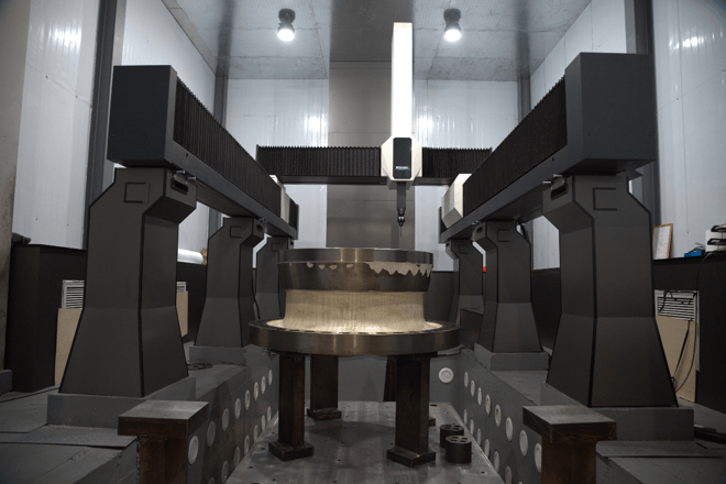


Alignment is the quietest — and most decisive — step in the entire coordinate measuring process.
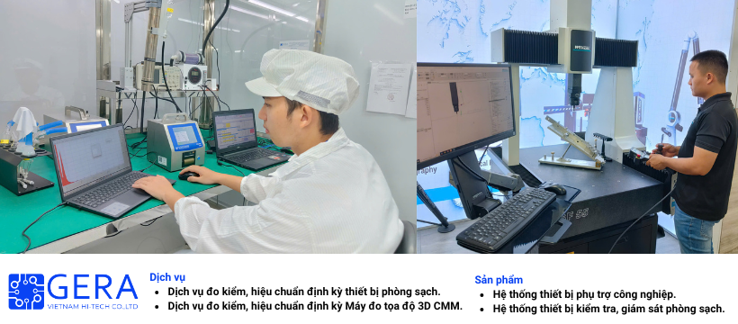
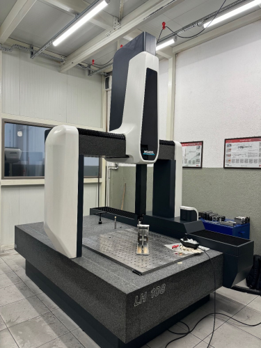
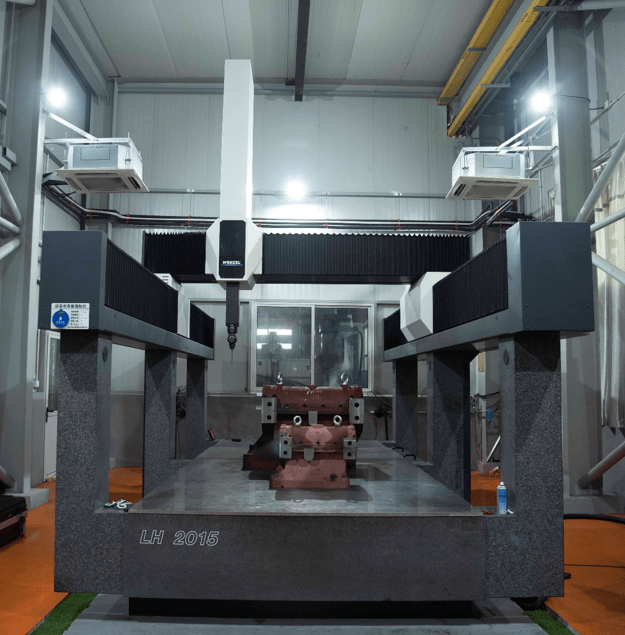
Working directly with CMMs (Coordinate Measuring Machines) at Gera Vietnam, I have seen more than a few cases where the machine was flawlessly calibrated, its geometric errors fully mapped and compensated, well within the manufacturer’s specification — and yet the measurement report still came out completely wrong. In most cases, the cause is not the machine itself. It lies in a step that happens before any actual measurement begins: part alignment.
What Alignment Really Is
When a part is placed on the CMM table, the machine has no idea where the part is or how it is oriented — it only “sees” its own coordinate origin, established through the equipment’s referencing. Alignment is the process of translating that arbitrary position of the part in the working volume into the coordinate system the designer had in mind when assigning dimensions and tolerances on the drawing — in other words, the datums.
A free object in space has 6 degrees of freedom — three translations and three rotations. This is exactly what the alignment step needs to lock down before any measurement of position, perpendicularity, parallelism, or profile can make sense.
The Classic Method: 3-2-1
The most common way to lock these 6 degrees of freedom is the 3-2-1 alignment method:
- 3 points on the primary datum — usually a plane — lock 3 degrees of freedom: the translation perpendicular to the plane and the two tilt rotations relative to it.
- 2 points on the secondary datum — usually a line or edge — lock 2 more degrees of freedom: the remaining rotation around the primary datum’s axis, and one lateral translation.
- 1 point on the tertiary datum locks the last degree of freedom: the remaining translation along that line.
For complex, flexible, or sheet-metal parts, other strategies — such as best-fit alignment or RPS (Reference Point System) — achieve the same result through more sophisticated methods. But the underlying principle never changes: reconstruct, inside the machine, the exact reference frame the designer defined on paper.
Why This Matters So Much
Every geometric tolerance — position, perpendicularity, parallelism, profile — is defined relative to a datum. If alignment reconstructs the wrong reference frame, every measurement taken afterward is comparing the part against a “zero” that isn’t the right zero. And the worst part: this happens even if the machine touches every point with absolute physical precision. This is not a problem of measurement accuracy — it’s a problem of answering the wrong question.
How a Tiny Error Destroys the Result
Here lies the detail that surprises most people outside the field of metrology: an alignment error almost never shows up as an obvious deviation. It appears as a minimal rotation — just a few hundredths of a degree — practically imperceptible even in the very points used to perform the alignment.
The problem is that angular errors don’t stay the size they started at — they grow with distance. A rotation error of just 0.01°, projected 500 mm away from the alignment point, already produces a position deviation of nearly 90 micrometers (µm) — several times larger than the tolerance of many critical features. And 0.01° is an error that almost no one would notice just by looking at the alignment points on the software screen.
The Practical Consequences
A poor alignment produces two types of damage — and the second is far more dangerous than the first:
- Good parts get rejected (false reject) — unnecessary rework and scrap, plus a “process investigation” chasing a problem that doesn’t exist in the part, only in the measurement.
- Bad parts get accepted (false accept) — the truly serious scenario: a feature that is out of tolerance moves on to assembly, to the customer, into a critical system, backed by an inspection report that looked perfectly clean.
What Actually Protects Against This
No CMM software can, on its own, decide which datums make functional sense, how many points are enough, or whether the spatial distribution of those points is robust enough to avoid amplifying error. That is a matter of engineering judgment — and judgment comes from proper training and hands-on experience.
This is why machine calibration and part alignment are two halves of the same quality assurance: one takes care of the machine, the other takes care of the operator. And between the two, alignment is the one that has to be redone with every new part, every new setup — which, in practice, makes it even more dependent on a well-trained metrologist.
Conclusion
A flawlessly calibrated CMM, in the hands of a poorly thought-out alignment, can still produce wrong numbers — only now they carry an appearance of certainty that makes them even more dangerous. Before trusting any measurement report, it’s always worth asking: was this part aligned correctly?
At Gera Vietnam, strict control over the alignment process before every CMM measurement is a key factor in ensuring the reliability of inspection reports, reducing the risk of false rejections, and preventing defective parts from reaching the market.